Digital Electronics Cheatsheet – Logic Gates, Flip-Flops, K-Maps
Introduction
Digital Electronics is one of the core subjects in Electronics and Communication Engineering (ECE), Electrical Engineering (EE), and Computer Science Engineering (CSE). Whether you’re preparing for semester exams, lab viva, or competitive exams like GATE, a quick revision cheatsheet can save you hours of study time.
In this blog, we’ve created a Digital Electronics Cheatsheet that covers:
- Logic Gates (the building blocks of digital circuits)
- Flip-Flops (fundamental memory elements)
- Karnaugh Maps (K-Maps) (used for Boolean simplification)
This guide is concise, beginner-friendly, and exam-focused. Let’s dive in.
Basics of Digital Electronics
Before we jump into gates and flip-flops, let’s quickly revise the fundamentals.
- Digital vs Analog Signals
- Digital: Discrete values (0 or 1, ON or OFF)
- Analog: Continuous range of values
- Binary System
- Base: 2
- Digits: 0, 1
- Example: (1011)₂ = (11)₁₀
- Boolean Algebra
- Mathematical tool for digital logic
- Variables: A, B, C…
- Operations: AND (·), OR (+), NOT (‘)
Logic Gates Cheatsheet
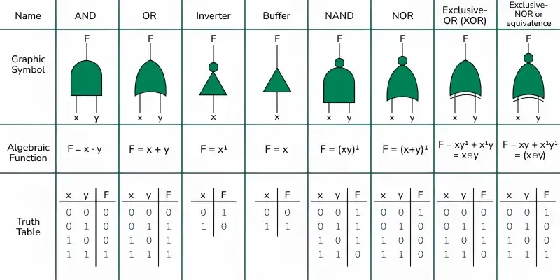
Logic gates are the building blocks of digital electronics. Each gate performs a basic Boolean operation.
Basic Logic Gates
- AND Gate
- Output is 1 only if all inputs are 1.
- Boolean Expression: Y = A · B
- OR Gate
- Output is 1 if at least one input is 1.
- Boolean Expression: Y = A + B
- NOT Gate (Inverter)
- Output is the complement of input.
- Boolean Expression: Y = A’
Universal Gates
- NAND Gate
- Output is complement of AND.
- Y = (A · B)’
- Universal gate: Can implement all other gates.
- NOR Gate
- Output is complement of OR.
- Y = (A + B)’
- Universal gate: Can implement all other gates.
Exclusive Gates
- XOR (Exclusive OR)
- Output is 1 when inputs are different.
- Y = A ⊕ B
- XNOR (Exclusive NOR)
- Output is 1 when inputs are same.
- Y = (A ⊕ B)’
Truth Table Summary
| Gate | Expression | Condition for Output = 1 |
|---|---|---|
| AND | A · B | Both inputs 1 |
| OR | A + B | At least one input 1 |
| NOT | A’ | Input = 0 |
| NAND | (A · B)’ | Unless both 1 |
| NOR | (A + B)’ | Both inputs 0 |
| XOR | A ⊕ B | Inputs different |
| XNOR | (A ⊕ B)’ | Inputs same |
Flip-Flops Cheatsheet
Flip-flops are sequential logic circuits that store 1-bit of information. They are used in registers, counters, and memory elements.
SR (Set-Reset) Flip-Flop
- Inputs: S (Set), R (Reset)
- Operation:
- S=1, R=0 → Q=1 (Set)
- S=0, R=1 → Q=0 (Reset)
- S=0, R=0 → No change
- S=1, R=1 → Invalid
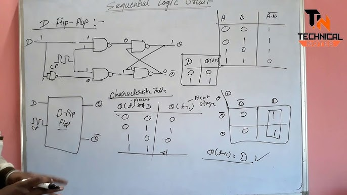
D (Data/Delay) Flip-Flop
- Input: D
- Operation: Output follows input (Q = D) on clock edge.
- Used for data storage and registers.
JK Flip-Flop
- Inputs: J, K
- Operation:
- J=0, K=0 → No change
- J=0, K=1 → Reset
- J=1, K=0 → Set
- J=1, K=1 → Toggle
T (Toggle) Flip-Flop
- Input: T
- Operation:
- T=0 → No change
- T=1 → Toggle Q
- Derived from JK Flip-Flop by connecting J=K=T.
Summary of Flip-Flops
| Flip-Flop | Inputs | Operation | Application |
|---|---|---|---|
| SR | S, R | Set/Reset | Latches |
| D | D | Data storage | Registers |
| JK | J, K | Set/Reset/Toggle | Counters |
| T | T | Toggle | Frequency division |
Karnaugh Maps (K-Maps) Cheatsheet
K-Maps are a method of simplifying Boolean expressions and minimizing logic circuits.
Basics of K-Map
- Grid format representation of truth tables.
- Adjacent cells differ by only one variable.
- Grouping reduces expressions into simplest form.
K-Map Rules
- Group cells in powers of 2 (1, 2, 4, 8…).
- Groups should be as large as possible.
- Groups can overlap.
- Wrap-around allowed (edges are adjacent).
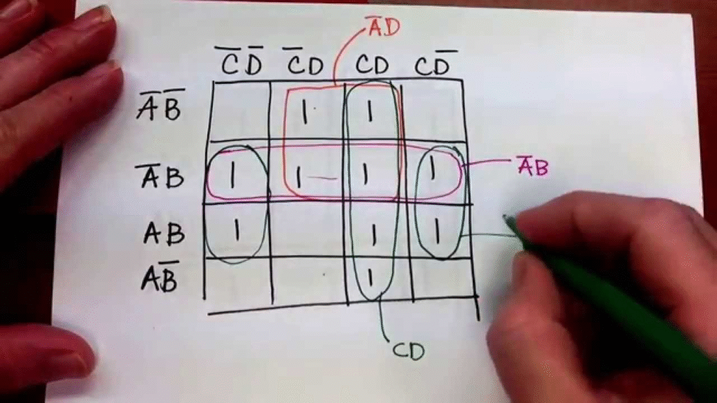
Example – 3-Variable K-Map
Given F(A,B,C) = Σ(1,2,3,5,7)
K-Map grouping → Simplified expression:
F = A’C + AB
Applications of K-Maps
- Circuit simplification
- Reducing cost and power consumption
- Used in combinational circuit design (adders, multiplexers, etc.)
Quick Revision Notes (One-Page Cheatsheet)
- Logic Gates: AND, OR, NOT, NAND, NOR, XOR, XNOR
- Universal Gates: NAND, NOR
- Flip-Flops: SR, D, JK, T
- K-Map: Grouping method for simplification
- Applications: Used in digital circuits, counters, memory, registers
FAQs on Digital Electronics Cheatsheet
Q1. Why are NAND and NOR called universal gates?
A1. Because they can implement all other logic gates and Boolean functions.
Q2. What is the difference between latch and flip-flop?
A2. Latch is level-triggered while flip-flop is edge-triggered. Flip-flops are more reliable in sequential circuits.
Q3. What is the practical use of K-Maps?
A3. K-Maps help in reducing Boolean expressions, which minimizes gate count and saves hardware cost.
Q4. Which flip-flop is most commonly used in counters?
A4. JK and T flip-flops are commonly used in counters because of their toggle property.
Q5. Are XOR and XNOR gates available in IC form?
A5. Yes, standard ICs like 7486 (XOR) and 74266 (XNOR) are available in TTL family.
Conclusion
This Digital Electronics Cheatsheet provided a quick and structured overview of Logic Gates, Flip-Flops, and K-Maps — three of the most important topics for any engineering student.
Whether you’re revising for an exam, preparing for lab viva, or getting ready for placements, this guide will help you recall concepts faster and save valuable study time.
Keep this cheatsheet handy, and you’ll never miss out on scoring easy marks in Digital Electronics.
Author Profile
- At Learners View, we're passionate about helping learners make informed decisions. Our team dives deep into online course platforms and individual courses to bring you honest, detailed reviews. Whether you're a beginner or a lifelong learner, our insights aim to guide you toward the best educational resources available online.
Latest entries
 UncategorizedOctober 3, 2025AKTU BTech Important Questions & Notes
 Exam Revision NotesSeptember 24, 2025C++ Programming Cheatsheet – STL, OOP Concepts, Syntax
 Exam Revision NotesSeptember 22, 2025Java Programming Cheatsheet – Collections, OOP, Exceptions
 UncategorizedAugust 28, 2025BTech 1st Year Notes & Cheatsheets (Subject-Wise)